
Page 10 - 6742
P. 10
1.3 Type analysis of a mechanism
The mechanism’s number of degrees of freedom can be
determined by the next criterion
W = 3n – 2p 5 – p 4= 3·5 – 2·7 – 0 =1,
where n=5 – is number of mobile links; p 5=7 – is number of
5-th class kinematic pairs; p 4=0 – is number of 4-th class
kinematic pairs.
As we can see, W = 1, it means the mechanism has only one
input link – crank 1. Next, let’s divide the mechanism on type
groups. The links 4 and 5 enter into the first type group in
sequence of unplugging. The links 2 and 3 enter into the second
type group. Both of these type groups are the second class by
Artobolevsky classification. Therefore, the mechanism consists of
initial mechanism (frame 0, input link 1) and two type groups of
second class. It means this mechanism is a mechanism of second
class. Type formula for this mechanism looks like
І(0,1)→ІІ(2,3)→ІІ(4,5).
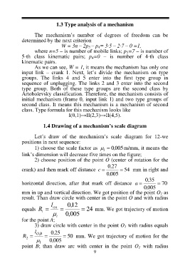
1.4 Drawing of a mechanism’s scale diagram
Let’s draw of the mechanism’s scale diagram for 12-we
positions in next sequence:
1) choose the scale factor as l 0, 005m/mm, it means the
link’s dimension will decrease five times on the figure;
2) choose position of the point O (center of rotation for the
0, 27
crank) and then mark off distance c 54 mm in right and
0, 005
0, 35
horizontal direction, after that mark off distance a 70
0, 005
mm in up and vertical direction. We got position of the point O 1 as
result. Than draw circle with center in the point O and with radius
l 0, 12
equals R OA 24 mm. We got trajectory of motion
1 0 005
for the point A; l
3) draw circle with center in the point O 1 with radius equals
l O 0, 25
1 B
R 2 0 005 50 mm. We got trajectory of motion for the
l
point B; than draw arc with center in the point O 1 with radius
9