Page 8 - 4560
P. 8

spatial  bending,  when  external  forces  act  in  different  planes
          (planes of bending moments at various cross-sections are oriented
          differently) and elastic beam line is a spatial curve.
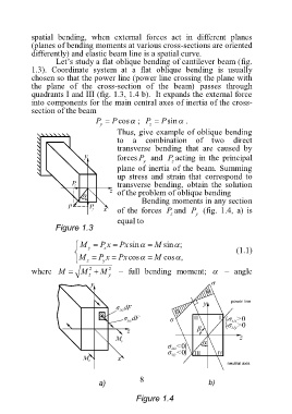
                 Let’s study a flat oblique bending of cantilever beam (fig.
          1.3).  Coordinate  system  at  a  flat  oblique  bending  is  usually
          chosen so that the power line (power line crossing the plane with
          the  plane  of  the  cross-section  of  the  beam)  passes  through
          quadrants I and III (fig. 1.3, 1.4 b).  It expands the external force
          into components for the main central axes of inertia of the cross-
          section of the beam
                             P   P cos ;   P   P  sin .
                              y             z
                                   Thus, give example of oblique bending
                                   to  a  combination  of  two  direct
                                   transverse  bending  that  are  caused  by
                                   forces P   and  P acting  in  the  principal
                                          y       z
                                   plane of inertia of the beam. Summing
                                   up  stress  and  strain  that  correspond  to
                                   transverse  bending,  obtain  the  solution
                                   of the problem of oblique bending
                                          Bending moments in any section
                                   of  the  forces  P and  P   (fig.  1.4,  a)  is
                                                  z      y
                                   equal to
                 Figure 1.3

                        M   P x   Px sin   M  sin ;
                               z
                          y
                                                                    (1.1)
                       M   P x   Px  cos   M  cos ,
                               y
                          z
                           2
                                2
          where  M     M    M   –  full  bending  moment;     –  angle
                           z    y


                                         8
                             a)                                         b)

                                        Figure 1.4
   3   4   5   6   7   8   9   10   11   12   13