
Page 44 - 4560
P. 44
considered positive if it increases the curvature of the rod, that
stretches the outer fibers. Diagrams M to construct the
compressed fibers.
In fig. 4.1 indicated positive trends of internal force factors.
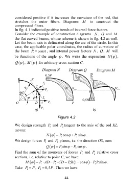
Consider the example of construction diagrams N , Q and M
the flat curved beams, whose scheme is shown in fig. 4.2 as well.
Let the beam axis is delineated along the arc of the circle. In this
case, the applicable polar coordinates, the radius of curvature of
the beam R const , and internal power factors N , Q , M will
be functions of the angle . We write the expression N ,
Q M
, for arbitrary cross-section C.
Figure 4.2
We design strength P and P tangent to the axis of the rod KL,
1 2
mourn:
N P 1 cos P 2 sin .
We design forces P and P planes, i.e. the direction OS, sum:
1 2
Q P 1 sin P 2 cos .
Find the sum of the moments of forces P and P relative cross
1 2
sections, i.e. relative to point C, we have:
M P AD P CD 2 PR 1 cos P R 2 sin .
1
1
Take P P , P 0,5P . Then we have
1 2
44