
Page 45 - 6742
P. 45
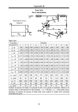
Appendix B
Task №14
Servo mechanism
Input data
Variables Variants
designation 1 2 3 4 5 6 7 8 9 10
а, m 1,200 1,400 0,900 0,800 0,700 0,600 1,000 1,100 1,200 1,300
b, m 1,100 0,550 0,300 0,350 0,250 0,150 0,400 0,450 1,500 0,525
c, m 1,300 0,750 0,700 0,800 0,500 0,550 0,600 0,650 0,700 0,400
l , m 0,275 0,290 0,150 0,190 0,200 0,170 0,220 0,265 0,315 0,250
OA
l , m 1,525 1,440 0,950 0,900 0,800 0,790 1,200 0,960 1,940 1,450
AB
l , m 1,140 0,625 0,700 0,600 0,500 0,550 0,625 0,650 0,750 0,675
BC
l , m 1,140 0,450 0,550 0,500 0,350 0,400 0,500 0,525 0,550 0,380
СD
l , m 0,720 0,500 0,450 0,400 0,350 0,500 0,400 0,615 0,550 0,500
DЕ
l ЕM , m 0,000 0,050 0,100 0,150 0,100 0,080 0,100 0,125 0,120 0,000
, град 165 180 190 170 175 150 160 195 145 170
n ,rpm 40 45 120 60 80 50 70 110 100 90
1
G 5 , N 400 460 500 520 540 350 420 600 550 580
F, kN 10 20 30 200 150 100 80 70 60 90
2
J O , kgm 35 45 45 49 55 60 59 67 58 49
Center of masses for link 3 is placed on the cross point of medians. Masses of
simple links is determined by the formula - m 10 l i . J O – equivalent mass
kg
i
moment of inertia for group of links that were joined to crank with constant
transmission ratio.
44