
Page 42 - 6742
P. 42
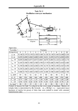
Appendix B
Task № 11
Oscillation conveyer mechanism
Input data
Variables Variants
designation 1 2 3 4 5 6 7 8 9 10
а, m 0,140 0,155 0,150 0,120 0,100 0,120 0,130 0,160 0,200 0,220
b, m 0,050 0,080 0,060 0,000 0,080 0,022 0,050 0,070 0,080 0,090
l , m 0,050 0,060 0,075 0,075 0,085 0,070 0,085 0,120 0,120 0,170
OA
l , m 0,430 0,500 0,300 0,300 0,390 0,3150 0,400 0,500 0,440 0,480
AB
l , m 0,350 0,400 0,220 0,280 0,350 0,270 0,390 0,450 0,365 0,450
CB
l , m 0,250 0,200 0,200 0,270 0,200 0,255 0,300 0,350 0,320 0,350
CD
l , m 0,800 0,750 0,400 0,500 0,450 0,400 0,500 0,600 0,600 0,700
DE
n ,rpm 55 58 42 64 75 50 60 40 35 48
1
G 5 , N 300 320 280 360 400 420 480 500 550 600
0,75 1,00 1,25 1,35 1,50 0,90 1,40 1,60 1,80 2,00
F 1 , kN
0,50 0,50 0,40 0,50 0,50 0,30 0,45 0,80 0,70 1,20
F 2 , kN
2
J O , kgm 30 25 35 22 19 42 28 50 45 38
Center of masses for link 3 is placed on the cross point of medians. Masses of
simple links is determined by the formula - m 10 l i . J O – equivalent mass
kg
i
moment of inertia for group of links that were joined to crank with constant
transmission ratio.
41