
Page 41 - 6742
P. 41
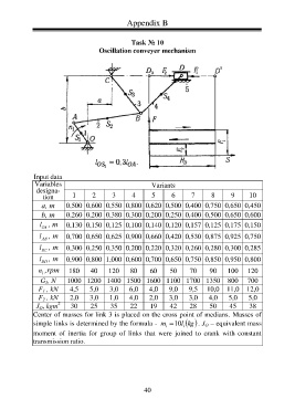
Appendix B
Task № 10
Oscillation conveyer mechanism
Input data
Variables Variants
designa-
tion 1 2 3 4 5 6 7 8 9 10
а, m 0,500 0,600 0,550 0,800 0,620 0,500 0,400 0,750 0,650 0,450
b, m 0,260 0,200 0,380 0,300 0,200 0,250 0,400 0,500 0,650 0,600
l , m 0,130 0,150 0,125 0,100 0,140 0,120 0,157 0,125 0,175 0,150
OA
l , m 0,700 0,650 0,625 0,900 0,660 0,420 0,530 0,875 0,925 0,750
AB
l , m 0,300 0,250 0,350 0,200 0,220 0,320 0,260 0,280 0,300 0,285
BC
l , m 0,900 0,800 1,000 0,600 0,700 0,650 0,750 0,850 0,950 0,800
ВD
n ,rpm 180 40 120 80 60 50 70 90 100 120
1
G 5 , N 1000 1200 1400 1500 1600 1100 1700 1350 800 700
4,5 5,0 3,0 6,0 4,0 9,0 9,5 10,0 11,0 12,0
F 1 , kN
2,0 3,0 1,0 4,0 2,0 3,0 3,0 4,0 5,0 5,0
F 2 , kN
2
J O , kgm 30 25 35 22 19 42 28 50 45 38
Center of masses for link 3 is placed on the cross point of medians. Masses of
simple links is determined by the formula - m 10 l . J O – equivalent mass
kg
i i
moment of inertia for group of links that were joined to crank with constant
transmission ratio.
40