
Page 43 - 6742
P. 43
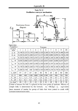
Appendix B
Task № 12
Oscillation conveyer mechanism
Input data
Variables Variants
designa-
tion 1 2 3 4 5 6 7 8 9 10
а, m 0,190 0,225 0,230 0,300 0,320 0,280 0,350 0,295 0,400 0,450
b, m 0,220 0,265 0,200 0,245 0,135 0,100 0,000 0,050 0,150 0,180
c, m 0,320 0,360 0,350 0,385 0,355 0,300 0,240 0,280 0,400 0,360
l , m 0,050 0,060 0,055 0,070 0,110 0,045 0,065 0,080 0,055 0,075
OA
l , m 0,210 0,240 0,305 0,350 0,330 0,305 0,355 0,340 0,415 0,425
AB
l , m 0,150 0,200 0,260 0,170 0,240 0,220 0,180 0,160 0,200 0,250
BC
l , m 0,280 0,340 ,360 0,380 0,340 0,290 0,230 0,270 0,380 0,320
СD
n ,rpm 57 47 67 60 50 70 45 40 80 100
1
G 5 , N 800 400 1100 1000 1200 1300 650 500 750 700
F 1 , kN 1,1 1,2 1,5 2,5 2,4 3,6 3,9 4,5 5,7 9,0
F 2 , kN 0,2 0,3 0,2 0,5 0,4 0,6 0,7 1,5 2,1 3,0
2
J O , kgm 30 25 35 22 29 42 28 50 45 38
Center of masses for link 3 is placed on the cross point of medians. Masses of
simple links is determined by the formula - m 10 l i . J O – equivalent
kg
i
mass moment of inertia for group of links that were joined to crank with
constant transmission ratio.
42