
Page 22 - 6742
P. 22
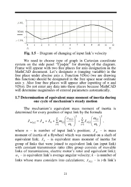
Fig. 1.5 – Diagram of changing of input link’s velocity
We need to choose type of graph in Cartesian coordinate
system on the side panel “Графік” for drawing of the diagram.
Frame will appear with two free places for axis designation in the
MathCAD document. Let’s designate n (ranging variable) in the
free place under abscise axis x. Function VD(n) (we are drawing
this function) should be designated in the free space near ordinate
axis y. Also four free places will appear after inputting of n and
VD(n). Do not enter any data into these places because MathCAD
will determine magnitudes of entered parameters automatically.
1.7 Determination of equivalent mass moment of inertia during
one cycle of mechanism’s steady motion
The mechanism’s equivalent mass moment of inertia is
determined for every position of input link by the formula
k S 2 k i 2
і
J зв n J м J 0 m J S ,
i
i
i 1 1 i 1
1
where n – is number of input link’s position; J – is mass
м
moment of inertia of a flywheel which was mounted on a shaft of
equivalent link; J – is equivalent mass moment of inertia for
0
group of links that were joined to equivalent link (an input link)
with constant transmission ratio (this group consists of movable
links of transmissions, electric motor’s rotor and equivalent link);
– is equivalent link’s average angular velocity; k – is number of
1
links whose mass considers into calculations; J S і – is і-th link’s
21