Page 46 - 6685
P. 46

P bh2   P bh1   oil                       w


             B      
                                                                      P
                                                                       f

                      
                                          L 0-F         L D-0
                    L 1 2-     L F-1

                  2       1             F        О                   D


                             Q+Q   2
                               1
                                                                     P
                                                                  f
             Q 2        Q 1  F_1       0-F            D-0
                      

                   P bh2    P bh1
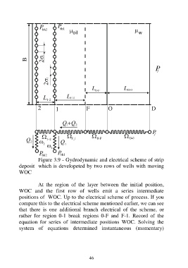
                  Figure 3.9 - Gydrodynamic and electrical scheme of strip
          deposit  which is developeted by two rows of wells with moving
          WOC

                  At  the  region  of  the  layer  between  the  initial  position,
          WOC  and  the  first  row  of  wells  emit  a  series  intermediate
          positions of  WOC. Up to the electrical scheme of process. If you
          compare this to the electrical scheme mentioned earlier, we can see
          that  there  is  one  additional  branch  electrical  of  the  scheme,  or
          rather  for  region  0-1  break  regions  0-F  and  F-1.  Record  of  the
          equation  for  series  of  intermediate  positions  WOC.  Solving  the
          system  of  equations  determined  instantaneous  (momentary)


                                         46
   41   42   43   44   45   46   47   48   49   50   51