
Page 86 - 4822
P. 86
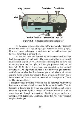
Figure 6.1 – Scheme horizontal separator

                  At the crude entrance there is a baffle slug catcher that will
           reduce  the  effect  of  slugs  (Large  gas  bubbles  or  liquid  plugs).
           However  some  turbulence  is  desirable  as  this  will  release  gas
           bubbles faster than a laminar flow.
                  At the end there are barriers up to a certain level to keep
           back the separated oil and water. The main control loops are the oil
           level control loop (EV0101 20 above) controlling the oil flow out
           of  the  separator  on  the  right,  and  the  gas  pressure  loop  at  the
           top.(FV0105 20 above) These  loops are operated by the Control
           System [19]. An important function is also to prevent gas blow-by
           which happens when low level causes gas to exit via the oil output
           causing high pressure downstream. There are generally many more
           instruments and control devices mounted on the separator. These
           will be discussed later.
           The liquid outlets from the separator will be equipped with vortex
           breakers to reduce disturbance on the liquid table inside. This is
           basically a flange trap to break any vortex formation and ensure
           that only separated liquid is tapped off and not mixed with oil or
           water drawn in though these vortices. Similarly the gas outlets are
           equipped with demisters, essentially filters that will remove liquid
           droplets in the gas.


                                          86