
Page 32 - 6685
P. 32
In order to calculated indicators met the real, in terms of
schematic design must adhere to the following conditions:
1) reserves oil of real and schematic deposits should be
the same;
2) perimeters of real and schematic deposits should be the
same;
3) a number of wells schematic and real deposits must be
the same.
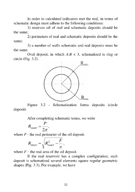
Oval deposit, in which A:B < 3, schematized is ring or
circle (Fig. 3.2).
Figure 3.2 - Schematization forms deposits (circle
deposit)
After completing schematic terms, we write
P
R ,
outer
2
where P - the real perimeter of the oil deposit.
F
R R 2 ,
outer
inner
where F – the real area of the oil deposit.
If the real reservoir has a complex configuration, such
deposit is schematized several elements square regular geometric
shapes (Fig. 3.3). For example, we have
32