
Page 34 - 6742
P. 34
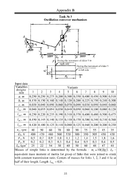
Appendix B
Task № 3
Oscillation conveyer mechanism
Input data
Variables Variants
designa-
tion 1 2 3 4 5 6 7 8 9 10
а, m 0,250 0,250 0,275 0,200 0,300 0,350 0,400 0,450 0,500 0,510
b, m 0,170 0,150 0,160 0,140 0,120 0,200 0,225 0,750 0,240 0,300
с, m 0,020 0,040 0,050 0,060 0,070 0,090 0,020 0,050 0,040 0,060
l , m 0,040 0,035 0,054 0,030 0,040 0,050 0,060 0,100 0,080 0,120
OA
l , m 0,250 0,220 0,235 0,190 0,310 0,370 0,400 0,480 0,500 0,475
AB
l , m 0,150 0,145 0,140 0,135 0,110 0,170 0,200 0,240 0,210 0,260
BC
l , m 0,120 0,100 0,125 0,110 0,080 0,125 0,160 0,200 0,200 0,250
СD
n , rpm 40 50 60 70 80 90 75 55 45 35
1
G 5 , N 400 420 480 500 520 300 350 505 450 420
F 1 , N 0,5 0,7 0,9 1,0 1,1 1,2 1,4 1,5 1,8 1,6
F 2 , N 0,2 0,2 0,3 0,3 0,4 0,4 0,5 0,3 0,4 0,5
2
J O , kgm 25 22 54 30 40 50 60 48 47 41
Masses of simple links is determined by the formula - m 10 l i . J O –
kg
i
equivalent mass moment of inertia for group of links that were joined to crank
with constant transmission ratio. Centers of masses for links 1, 2, 3 and 4 lie at
half of their length. Length l 0, b 1 .
ES 5
33